
For architects and designers
The wall system
How our 300 × 150 mm hollow plank tiles could hang on a wall.
Brackets on chemical anchors carry slim posts. A horizontal hook beam runs behind every joint between rows. One extruded aluminium clip hooks over the beam at each joint and locates the tile below and the tile above. Tiles are lowered into place row by row, from the bottom up. Explore the layers and the sequence below.
From wall to tile,
layer by layer.
Drag the model to turn it. Separate the layers with the slider and follow the installation step by step.
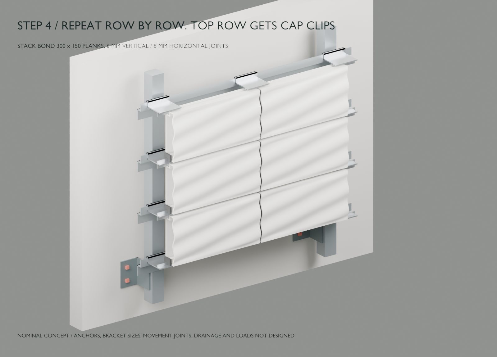
Nominal digital model of a two-column, three-row excerpt. Not a construction drawing.
Separates the layers outward from the wall.
Installation sequence
01 Frame
Drill and set the brackets with chemical anchors, and let the resin cure as the anchor maker specifies. Fix the posts plumb. Screw the hook beams to the posts, level, 158 mm apart.
02 Starter clips
Hook starter clips over the bottom beam. Slide each one to a vertical joint line, 306 mm apart, and lock it with one screw.
03 Lower row 1
Put a soft joint block on the first clip and lower the first tile straight down: its bottom slot drops over the blade. Put the next block against the tile end, lower the next tile, and continue along the row.
04 Clips into row 1
Hook the next clips over the next beam. One downward movement drops the hook over the beam and the lower blade into the top slots of row 1. Slide each clip to its joint and lock it.
05 Next rows, finished wall
Repeat for each row and finish with cap clips. Tiles are only ever lowered. Removing a single tile from the middle of the wall is not provided.
How one clip works
One aluminium extrusion with 3 mm walls, cut 74 mm long, hooks over the beam behind the tiles and carries the tile ends at a joint. Values are nominal results from the studio’s digital fit check. Fired ceramic tolerances are untested.
Hook seat 3 mm
The hook bar rests on the full 3 mm top of the beam’s front web. This sets the clip height with no measuring.
Lip gap 1.0 mm
The lip hangs 8 mm down behind the web, 1.0 mm clear of it. It stops the clip being pulled forward off the beam.
Blade clearance 1.5 mm
One straight blade goes 8 mm into the slot of the tile above and the tile below, with 1.5 mm clearance each side.
Bearing 816 mm² per tile end
The plate carries each tile end. A 5 mm gap under the plate means the lower tile carries nothing.
Slide 1 mm at most
A 5 mm soft block stands in each 6 mm vertical joint, so a tile can slide at most 1 mm along the clips.
What is not designed yet
This concept shows an installation idea and a fit between parts. Everything below needs an engineer, physical testing, or both.
- Strength. The clip hook and its eccentric load, beam spans between posts, and post and bracket sizes.
- Wind load. Suction on the tiles, clips and frame.
- Chemical anchors. Size, embedment and edge distance.
- Water. The upward-facing top slots can hold water and freeze. The beam return is another ledge and needs drain holes.
- Thermal movement. Expansion joints in long aluminium beams and movement joints in the tile field.
- Fixings. The lock screw type, and galvanic isolation where stainless steel meets aluminium.
- Tile length scatter. The soft joint block may see a 4 to 8 mm joint, and its material must cope.
- Ceramic. Fired-clay fit and shrinkage, and the strength of the slot lips.
- Edges. Wall ends, corners, openings and the open tile ends.
- Replacement. Removing a single tile from the middle of a wall is not provided.
- Review. This revision has not yet been checked by an independent reviewer.
Considering ceramic relief for a project? We’d be glad to talk it through with you and your engineer.
Start a design conversation