Fairy Martin

Studio notes · Brisbane, October 2026

How a tile
gets worked out.

One printed ceramic tile, revised in the open. Each note records what we tried, what it taught us and why the next revision changed.

Every image here is a digital render or diagram from our own models, with nominal dimensions. Nothing on this page has been printed in clay, fired or installed yet. Physical clay trials are next, and their films will appear below as they run.

What the models taught us so far

  1. r07

    Print it standing on its end.

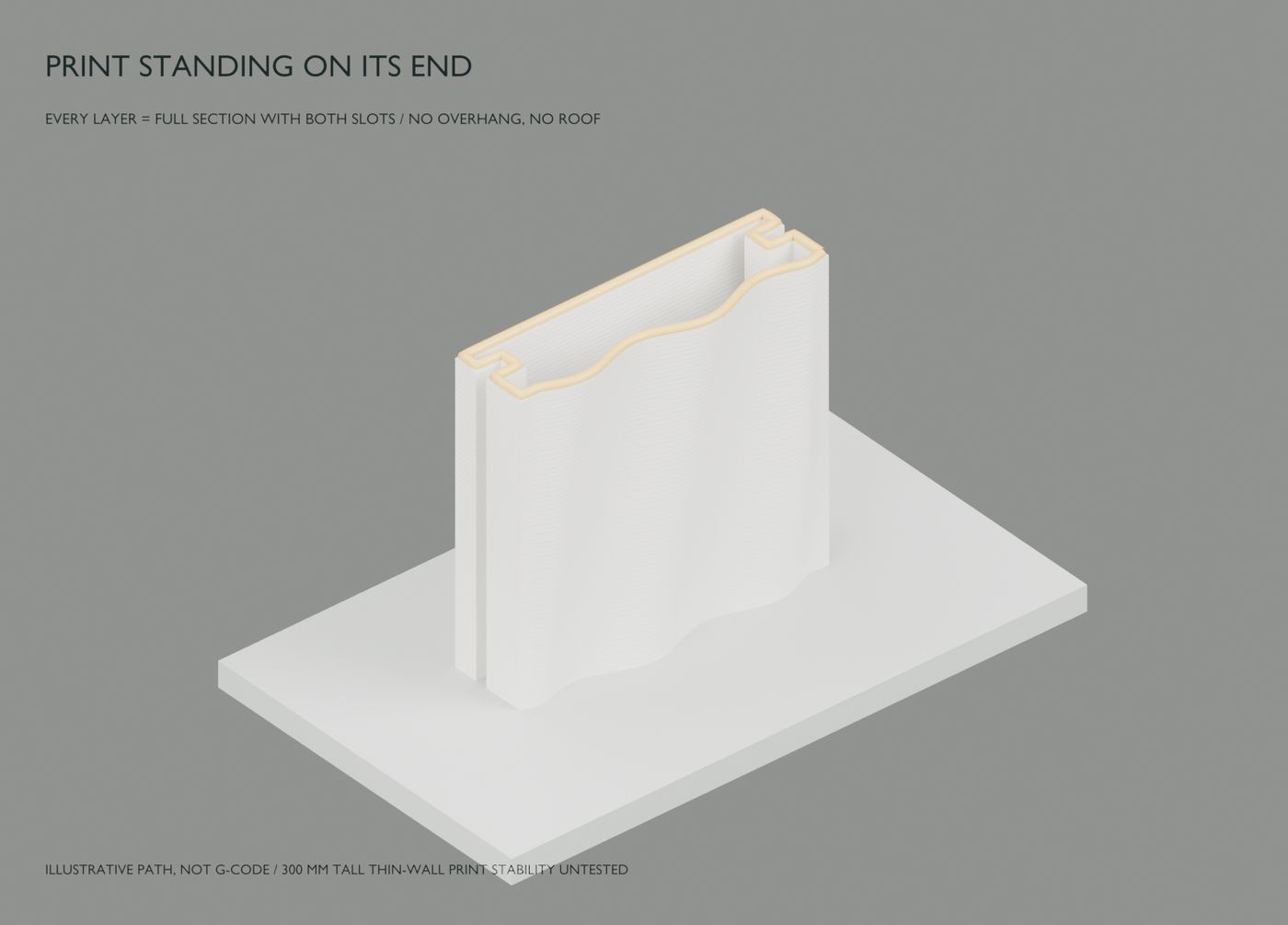
    Every layer is then the full closed section, rear slots included, so nothing overhangs and nothing needs support.

  2. r07

    Relief along the length is limited.

    Each 2 mm layer can step out only about 1 mm from the one below. Relief across the height is free, because it lives inside one layer.

  3. r06–r07

    Build the wall from the bottom up.

    One shared clip in each horizontal joint holds the tile below and carries the tile above. Tiles are only ever lowered into place.

  4. r10

    From screws to a hook.

    The clip now hooks over a horizontal beam on a frame fixed with chemical anchors, and slides to its joint before one screw locks it.

The revisions,
newest first.

Eleven digital studies. Dates are as recorded in each model’s notes; two revisions were not dated.

  1. The clip hooks over a beam

    Instead of screwing every clip to a vertical rail, r10 hooks the back of the clip over a horizontal aluminium beam, one behind each horizontal joint. The beams sit on posts and brackets fixed to the wall with chemical anchors. The hook sets the clip height with no measuring or drilling, and each clip slides along the beam to its joint, so it can follow tiles of slightly different lengths before one screw locks it.

    Not yet reviewed independently. Anchors, beams, brackets and all loads still need a facade or structural engineer.
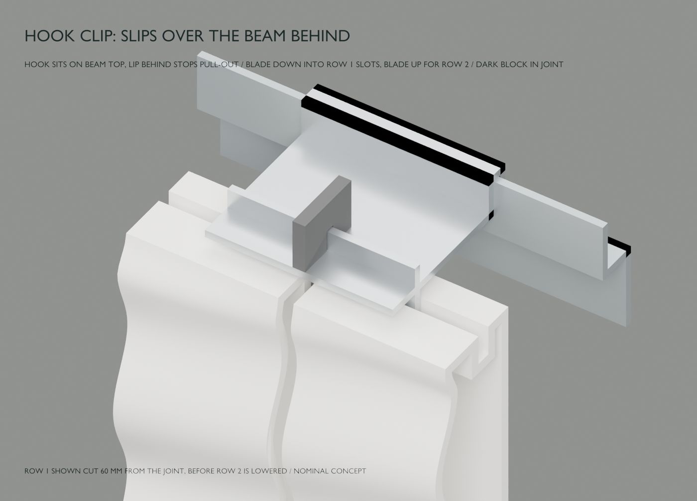
    An aluminium clip hooked over a horizontal beam, its lower blade dropped into the top slots of two white wave-relief tiles, with a dark soft block standing in the joint between them
    Digital render · hook clip close-up
  2. Back to one straight blade

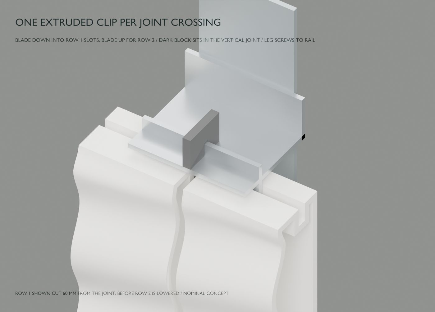
    Set beside the r07 drawing, the r07 clip was preferred: a plate with one straight blade through both slots. r09 makes that profile as an aluminium extrusion cut into 74 mm pieces, screwed to vertical rails, with a soft block in each vertical joint to stop tiles sliding along their slots. Review found the 5 mm gap under each plate depended only on where the screw holes sat on the rail. The next revision replaced the screws with a hook.

    An extruded aluminium clip screwed to a vertical rail, its blade in the top slots of two white tiles and a dark block in the vertical joint
    Digital render · extruded clip on a vertical rail
  3. How a whole wall goes up

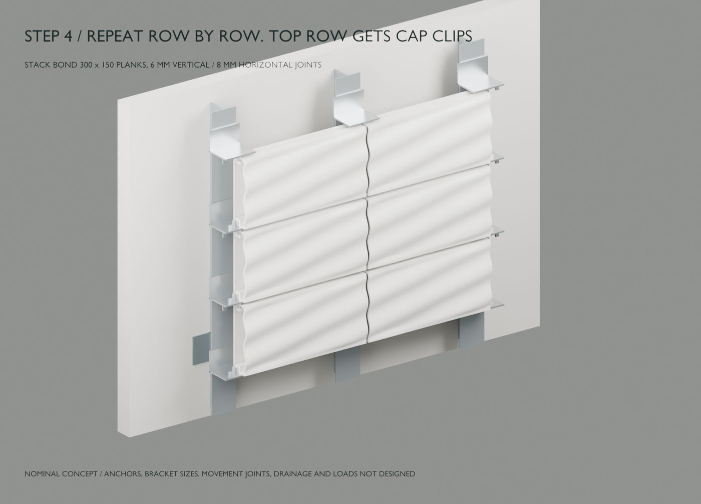
    With the tile section settled, the question became the wall. r08 chose stack bond, an aluminium rail on every vertical joint and one clip at each joint crossing, cut from 3 mm sheet and bent, with tongues for the slots and fins to stop sideways sliding. It passed its nominal fit checks, but the r07 clip section was preferred the same day, so r08 is kept as a record.

    Three rows of white wave-relief plank tiles in stack bond on vertical rails, with bent sheet clips at each joint and cap clips along the top
    Digital render · finished study wall
  4. A hollow plank that prints on its end

    A reference photo of a hollow ceramic plank gave us a section: a flat-backed box, 300 × 150 mm, with clip slots along both rear edges and our own wave, chevron and ripple fronts. Standing on one end, every 2 mm layer is the full closed section, both slots included, so the slots need no overhang or support.

    It also showed the method’s limit. Relief that changes along the length can step only about 1 mm per layer, which is why the ripple stays gentle; relief across the height is free. One shared clip in each horizontal joint holds the tile below and carries the one above, installed from the bottom up.

    A white hollow plank tile partly printed, standing on its end on a print bed, with the next closed layer outlined across its top showing the wavy front and both rear slots
    Digital render · partial print standing on its end
  5. Build from the bottom

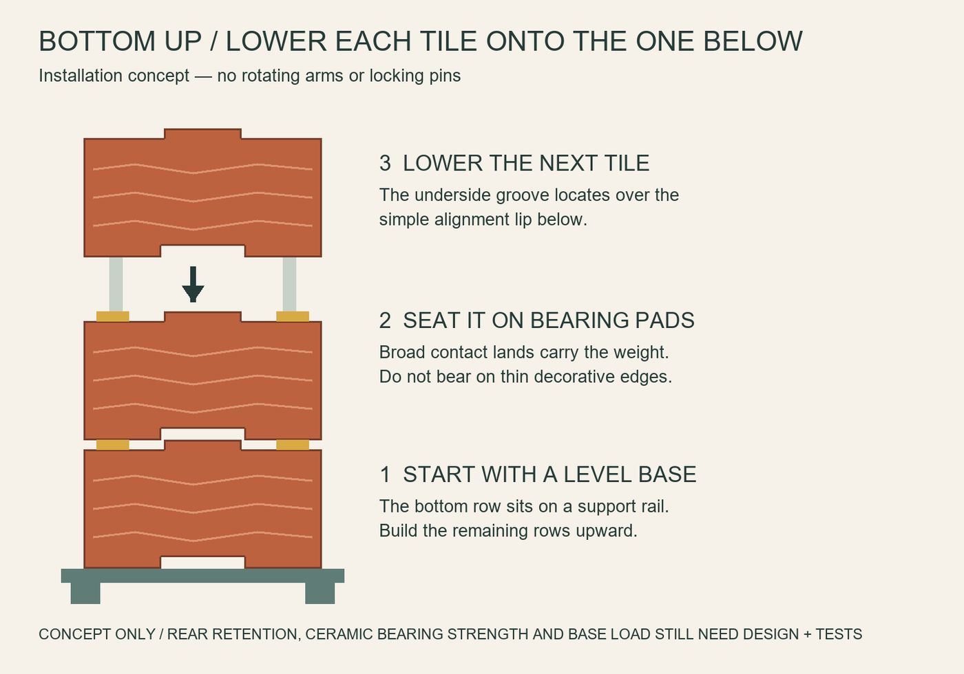
    r05 was too complex. The direction changed to gravity stacking: a level base row, then each tile lowered and seated in turn, with no rotating arms or locking pins. This is installation logic rather than finished CAD; rear retention, bearing strength and the load that builds up towards the base were left for the next model to resolve.

    A diagram of three terracotta-coloured tiles stacked on a level base rail, with three numbered steps: start with a level base, seat each tile on bearing pads, lower the next tile
    Digital diagram · stacking concept
  6. Straight in from the front

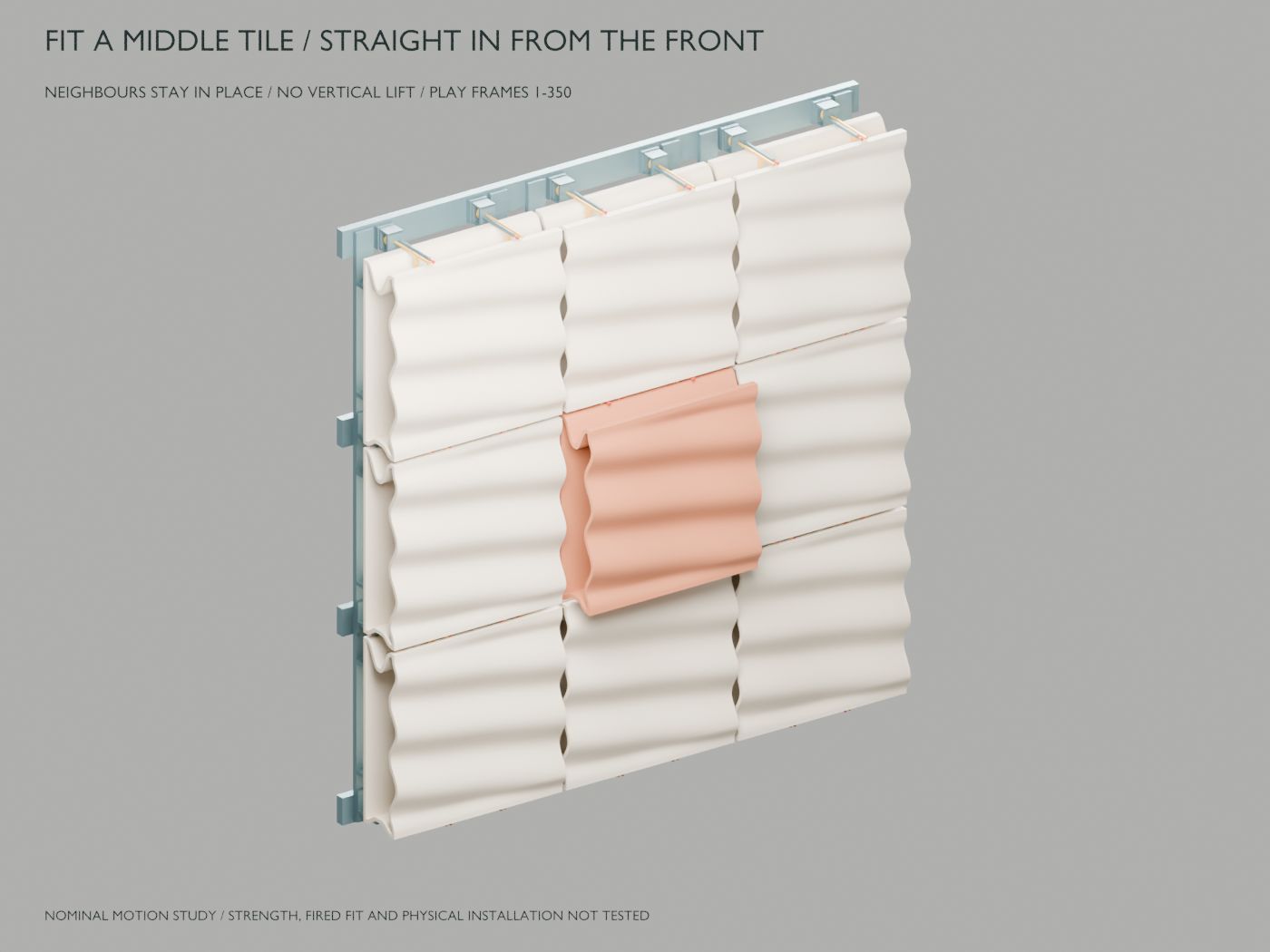
    r05 worked out how one middle tile could be fitted and removed from the front while its eight neighbours stay in place. The tile moves straight in at its final height, then four quarter-turn keepers and captive pins lock it. The digital sweep found no collisions, but every tile needed four retainers with two operations each, and it was set aside as too complex.

    A nine-tile study wall of pale wave tiles on rails, with the terracotta middle tile being pushed straight in from the front
    Digital render · middle tile insertion
  7. Clips, rails and a sideways print

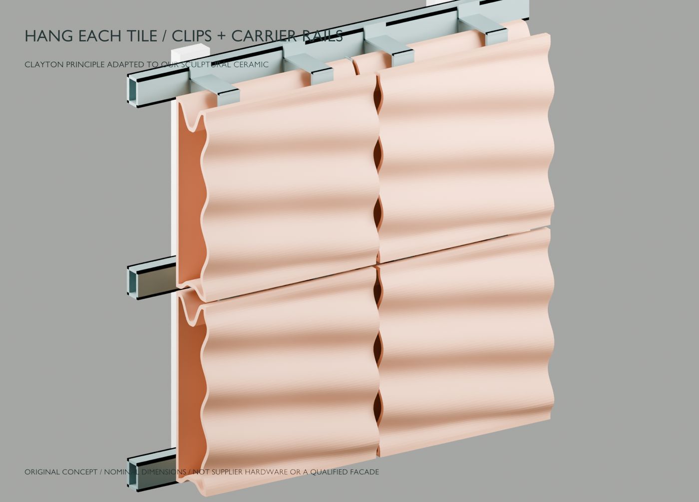
    A terracotta manufacturer’s technical manual showed tiles hung on clips fixed to horizontal rails, and r04 adapted that principle to our hollow tile with original geometry. To give the tile hanging grooves without overhangs, it prints standing on one side and turns 90 degrees to hang, so the grooves appear in every closed layer. The r03 side locks were left out, because they had not been shown to work with this installation movement.

    Two rows of peach-coloured wave tiles hanging on horizontal carrier rails with top, middle and bottom clips
    Digital render · clip and rail study
  8. One system, many patterns

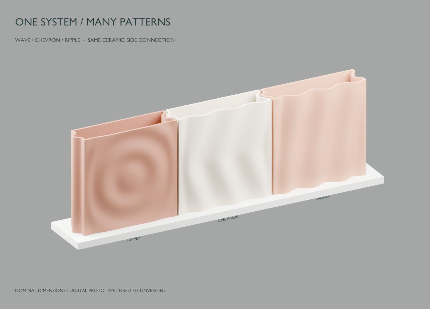
    r03 turned the hollow tile into a reusable generator. Wave, chevron and ripple fronts share the same rounded tongue-and-recess side edges, so different patterns can sit side by side. The generator refuses geometry that breaks its rules, including a layer that reaches more than 1 mm beyond the one below, though those limits are digital study values, not measured clay settings.

    Three hollow tiles side by side on a base, with ripple, chevron and wave fronts joined by matching tongue-and-recess side edges
    Digital render · wave, chevron and ripple family
  9. Start from the layers

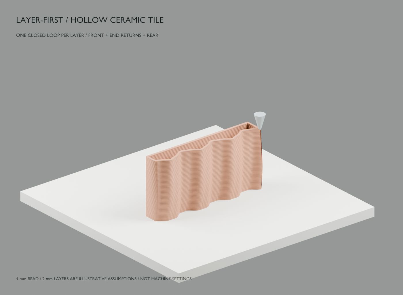
    The first sculptural model had not shown a believable layer-on-layer print. r02 starts from the process: every layer is one closed, unbranched loop around the wavy front, the ends and a straight rear, with an empty interior and nothing spanning the cavity. The 4 mm bead and 2 mm layers are illustrative assumptions, and mounting was left open because the old rib contacts did not transfer to a hollow form.

    A hollow wave-fronted tile half built from stacked clay-coloured layers on a print bed, with a representative nozzle at the corner
    Digital render · halfway through the layer stack
  10. A deeper sculptural tile

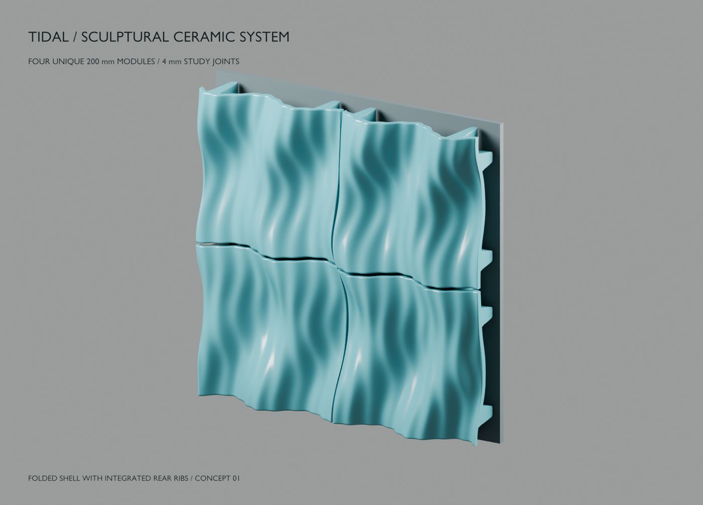
    The first sculptural concept explored four 200 mm modules with deep folds, open rear recesses and integrated rear ribs, hung on carriers and a wall rail. Printed upright, those horizontal rear ribs would print as unsupported overhangs. That correction is where the layer-first approach began.

    Four teal ceramic tiles with deep flowing folds forming a square panel, with rear ribs visible at the edge
    Digital render · four-tile sculptural field
  11. Files for a first trial

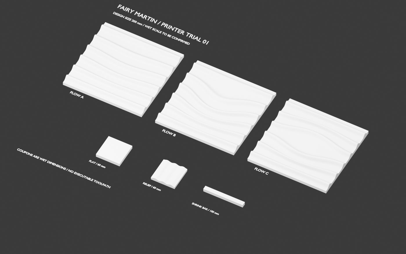
    We prepared a package for a proposed first clay printer trial: three 200 mm relief tiles and three small coupons for a flat base, a relief and shrinkage. The files carry no shrinkage compensation, and no trial was booked or machine ordered. Its central question still stands: can a printer repeatedly make this relief with an acceptable fired back and finish?

    Three white 200 mm relief tiles and three small test coupons laid out flat on a dark background
    Digital render · trial specimens

Print films

Real footage from the clay trials. Nothing here is rendered.

First physical print films will appear here as the clay trials run.

Digital first, clay next.

These notes describe nominal digital studies, not tested products. Fired fit, shrinkage, strength, fixings and anchors are not yet evaluated, and nothing here is an installation instruction. Fairy Martin is a studio in development in Brisbane; physical results will be added here as the trials run.